Modern Classic SLRs Series :
MD-4 Motor Drive for Nikon F3 Series models- Technical Information

Connections with Motor Drive

What are the functions of those electrical contacts at the base of the MD-4 ? Primarily, it is for communication by means of electrical pulses between the camera and the drive. Each contact has their respective purpose.

1) When MD is mounted, Power supply connector pushes up MD switch and thus cancels the power supply from the batteries installed in the camera. Thus MD is ready to supply Vcc1 to the circuit of the Nikon F3. 

2) Depressing the trigger button of MD halfway closes Power SW of MD to turn on the transistor for power supply. Next, MD allows Vccl of camera to go high to approx. 3 V. Simultaneously, the signal of power-ON is provided with the circuit of camera, and Vcc2 goes also high as Power SW of camera is closed.

MD SW.jpg (4k) MD SW.gif (5k)
3) When Vcc2 reaches Vccl, the signal of 16 sec.-holding is transferred back to MD. So MD will continue to supply Vccl to the camera.

4) Next, depressing the trigger button of MD all the way closes Release SW of MD. The signal drops the voltage of shutter release circuit of camera as Release SW is closed. Accordingly, Shutter is released.

5) After the closing curtain's travel completes, Closing curtain SW closes to provide MD with the signal of film-advancing through Closing curtain SW and Film-advance completion SW. Then, with a del (ON-delay) of approx. 22 ms, MD starts to work for film-advancing.

6) As soon as the film-advancing is started, Film-advance completion SW closes and then Closing curtain SW opens. Completing the film advancing, Film-advance completion SW opens. Now the voltages of both the SWs go high to provide a signal for stopping the operation of MD. At this moment, the film-advance mechanism of the camera also blocks MD mechanically, and Ending SW closes to stop MD electrically in approx. 15 ms before a delay (OFF-delay) of approx. 18ms.

7) In case the continuous setting of MD is in use, MD provides a signal for shutter releasing in approx. 15 ms after Film-advance completion SW opens. It functions after this step in the same manner as above.

Release timing

Timing

Condition

Standard

ON-delay

From the time when camera's closing curtain signal turn' on to the time when motor starts rotating.

22.5 +- 0.5ms

OFF-delay

From the time when camera's film-advance completion SW turns off to the time when motor stops

14.3 -35ms

Release timing

From the time when camera's film-advance completion SW turns off to the time when Release signal turns on.

15 +- 2ms

Note: If depressing the shutter release button, opened Closing curtain SW will not allow MD to start film-advancing before the release button is freed.

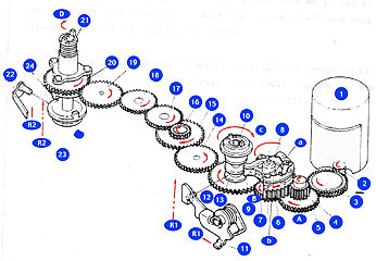
Mechanism - Driving Mechanism The MD-4 uses one motor to advance and rewind the film. But the clutch for advancing and rewinding allows the motor to rotate in the one direction. And, differing from the MD-2 and the MD-3, this motor drive unit releases the shutter by electric signal.

Film Advancing: Closing Trigger SW provides current flow for Motor (1) and then Motor (1) rotates. This power rotates Gears (3), (4) and (5). For vibration-reduction, Rubber (*) is attached to Motor (1). For noise-reduction, Gears (2), (3) and (4) are helical gears, providing excellent power transmission. Rotating Gear (5) in direction A drives Gear (6) Thus, Protrusion b of Clutch lever (8) pushes Claw a of Clutch (8). At this time, Gear (7) rotates in direction B. This turns Wind coupler (10) in direction C through Gear (9) for film-advancing. After completing the film-advancing, Wind coupler (10) is blocked by the camera. But Motor (1) still works, and it tensions Clutch torque spring, which allows Protrusion b of Clutch lever to run on Claw a of Clutch (8). Thus, Auto-stop SW closes and Motor (1) stops.

Film Rewind
: Setting Rewind slide (
1) pushes Rewind clutch lever (11) and Rewind lever shaft (12). This places Gear (13) upward to cancel Wind coupler (10) and to engage with Gear (14). Thus, the rotation of Motor (1) is transmitted from Gear (13) to Gear (20) through Gears (14), (15), (16), (17), (18) and (19). Next, setting Rewind slide (2) places Plunger (23) and Rewind coupling (21) upward. Protrusion underneath Gear (20) engages with Rewind clutch (23). Rewind coupling (21) rotates in direction D for rewinding the film.

Auto-stop Switch Film-advancing is performed by rotation of Clutch as earlier mentioned. When film-advancing completes -the camera Auto-stop SW (11) and (12) turn on to stop the motor. LED lights up . At the end of the film, the film tension allows Clutch torque spring to work, instead of the camera. Then Auto-stop SW will stop the motor in the same way as above. When Auto-stop SW works halfway in the film advancing cycle, the signal of film-advance keeps LED glowing. The MD-4 is provided with a safety device, which stops the motor in approx. 1 sec., unless Auto-stop SW works.

md4orangeillus.jpg
Mechanism behind frame counter settings, Film advance and Rewinding

Frame- counter Frame-counter is a subtractive type which shows the number of frames remaining. This counter sets the motor drive to cut off automatically at the end of the counter frame. When the frame-counter stops at the orange dot (called "Counter free Position"), the motor drive will work until the film goes to the end.

Film-advancing While film-advancing, Motor rotates Gear (1) in direction A. At this moment, Advance claw (3), coupled to Eccentric wind shaft (2), moves and returns to advance Counter gear (4) in direction C. Ratchet (5) then holds Counter gear. When Counter goes back to '0', Connector (7) of Printed circuit board (6) comes in contact with Counter switch (8) providing the rewind-stop circuit with the signal. It stops Motor.

Rewinding While rewinding, Gear (13) rotates in direction C. At this time, Advance claw (15), coupled to Eccentric gear (13), moves and returns to advance Counter gear in direction C. Frame counter goes from '0' to the orange dot and stops, because Counter gear lacks the teeth for advancing the frame counter at this position.


Standard LED voltage

.

Voltages in changing-over

Battery

(A) from two-light up to one-light up

(B) from one-light up to none

AA-type penlight

10.2 +- 0.2V

10.0 +- 0.2V

Ni-Cd MN-2

15.0 +- 0.7V

14.8 +- 0.7V


* The maximum operable voltage for the MD-4 at both S-C mode should be under 20V when connected to DC power supply. While minimum operable voltage is 7V when connected to DC power supply.

Note: when M-type penlight battery is in use, the voltage (A) is higher than the voltage (B) by 0.1 - 0.3V.

When Ni-Cd MN-2 is in use, the voltage (A) is higher than the voltage (B). Adjustments can be made by turning VR1 for the voltage (A) and VR2 for the voltage (B).


md4backillus.gif
Automatic Stop of Rewinding Film

You can do a quick check on the auto rewind stop feature if you suspect the connecting terminal is faulty by first: Put the film rewinding in operation, and then use a screw driver blade to short-circuit Auto rewind-stop terminals. At this moment, the motor stops immediately and one LED lights up. After returning Rewind slide 2, the LED turns off.

safetyillus.gif
Safety Device Operation Checking

Just like the other fine drives made by Nikon, the MD-4 also has a safety device built -in. ( Most common is during mounting with the motor and camera switch on). Short-circuit between Pin (5) and Pin (7) on Camera connector rotates the motor. In this condition, the motor automatically should stop in 680-1420 ms (i.e.0.68 -1.42 sec).


External Power Connector


Remote Control Connector


Use a screwdriver blade to short-circuit Pin 1 with Pin 2. Make sure that it releases the shutter.


NavBar
  |  |  |
  Back to Index of Nikon F3 Models
  Back to Pictorial History of Nikon SLRs
About this photographic site
Contributions and Credits
  Home - Photography in Malaysia


About this photographic site Contributions and Credits

  Home - Photography in Malaysia

Modern Classic SLRs Series :
MD-4 Motor Drive for Nikon F3 Series models- Technical Informatio
Copyright © 1999. leofoo ®. MIR Web Development Team.