AMP (Automatic
Multi-Pattern)
Process/Micro-electronics Technology

|
Modern
Classic SLRs Series : |
AMP (Automatic Multi-Pattern)
Process/Micro-electronics Technology
Phase I
Light Sensing and Digital Conversion:
Five sensors (Refer below for sensor at the center, while another separate sensor is for TTL Flash) corresponding to the five segments individually sense the light coming through the lens. These analog values are logarithmically compressed; then a High-Speed Sequential Comparison A/D (analog-to-digital) converter transforms them into digital values.* Also check two other sections:
(Various Metering system compared) follow by:
(How the AMP fares in various possible scenarios) (3 parts)Six photodiodes on two chips read subject brightness on the viewfinder screen for metering in "A," "S," and "P" modes. The pattern used divides the screen into five zones using two photodiodes for the center and one for each of the other four zones. The layout and photodiode connections are shown in the illustration below.

|
|
|
|
|
|
|
Loganrithmic Compression |
||||
|
PV0 |
PV1 |
PV2 |
PV3 |
PV4 |
|
High Speed Sequential Comparison A/D (Analog to Digital) Converter |
||||
Here's how the zone-by-zone A/D process works in the FA. The CPU causes a voltage to appear at the comparator's non-inverting input which is equivalent to a medium brightness, say BV-11. If the actual brightness is higher, the comparator's output will be low (remember the brightness voltage appears at the comparator's inverting input) and that low is sent back to the CPU. The CPU enters a "0" (for the low) into a register and this causes the D/A output code to change to a higher number equivalent to a higher voltage.
Now a higher voltage appears on the comparator's non-inverting input. If this is greater than BV voltage, the comparator switches high and a "1" is sent into the CPU's register. That causes the D/A code to switch to a lower voltage which is again compared to BV voltage. This trial and error process continues until the D/A voltage matches BV voltage which means a binary code exists for that particular brightness value.
Next, the CPU moves to another zone and repeats the routine until brightness is recorded for all five zones. The fast clocking speed enables the CPU to work quickly and keep a running account of subject brightness.
ISO, aperture setting, maximum aperture, shutter speed setting, and mode are all sent to the CPU on IC-3 as pure binary codes. Each wiper is a Gray Code generator, so there is no need for A/D conversion. From this data and BV, the CPU determines an exposure value (taking into account backlight etc.), then depending upon mode, it will select an appropriate aperture, shutter speed, or both. The FA uses the binary language of the computer in the form of a cyclic code to eliminate even the most minute reading errors in shutter speed, lens speed, film speed, number of stopped-down f-stops, etc.
Phase II
Lens data Input
Lens data including speed, type, number of stopped-down f-stops, focal length and digital light values are fed into this phase to accurately read brightness values over the entire frame area while compensating for the effects of vignetting, light fall-off, etc. Of the lens in use.
|
|
||||
|
|
||||
|
|
||||
|
|
||||
|
|
Phase III
Scene Evaluation
A great number of important data including degree of contrast, brightness composition patterns, extreme brightness position, percentage of bright areas, position and percentage of dark areas, light intensity of extreme brightness, etc., are evaluated in this phase in order to avoid making the socalled "foolproof" light reading characteristic of conventional metering systems in auto-exposure cameras.
Phase IV
Correct Exposure Parameters Analysis:
Parameters required to render optimally exposed pictures even in unfavorable lighting situations are analyzed and selected.
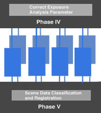
Phase V
Scene Data Classification and Registration:
Using the parameters selected in Phase IV, this phase classifies the picture-taking scene into a number of computer simulated scene patterns (drawn from a visual assessment of tens of thousands of pictures, computer analysis of the relationship between brightness patterns, optimum contrast, etc., and human evaluation); these are then registered.
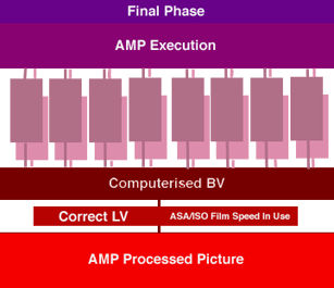
Final Phase
AMP Execution:
Scene data evaluated at Phase III is fed into this phase and compared with classified and registered Phase V scene data. The correct brightness value is then computerized.
|
Back |
to Nikon FA Main
Index Page
Camera Instruction Manual - HTML | PDF (1.4 MB)
Main Reference Map for Body - HTML | PDF (731k)
Specifications - HTML | PDF (245k)The AI-S Nikkors (related info | TTL OTF Flash Metering | Interchangeable Focusing Screens. The MD-15/MD12/MD11 Motor Drives | 3rd party Power Winder (new) | Flash Units -SB-16 | SB-15 | SB-10 | SB-16B & Other Options | Databacks | Titanium Shutter | Variation : Mr Y K Wong from Singapore contributing 11 images of his Nikon FA GOLD
| Nikon FM series | Nikon FE series | Nikon FA |
W A R N I N G: The New G-SERIES Nikkor lenses have no aperture ring on the lens, they CANNOT ADJUST APERTURES with any of these manual focus Nikon FE series SLR camera models; please ignore some portion of the content contained herein this site where it relates.
| Nikkor Resources || Message Board | for your favourite Nikon FA camera
| Message Board | for your Nikon Optics in a shared environment
| Message Board | Specifically for Dispose or Looking for Nikon / Nikkor Photographic Equipment
A contributing effort to Michael Liu's Classic Nikon SLR camera site.
Credit: Lars Holst Hansen who is co-maintaning the site; MClau, who patched a lot of mistakes for me on earlier stage of the site; Miss Rissa Chan - Marketing Manager and the members of technical service team of Shriro Malaysia (now Nkon Corporation Malaysia); Mr Terence HM Tan for his FA/MD15 images; Mr Victor for his Nikon FA body, EEwyn, my nephew for some of the scanning work; Mis Wati/Mis Mirza for their help on the OCR work on the instruction manual section - We all had some real good times on the construction of this site. Dave Hoyt who prepared the introductory page. Note:certain content and images appeared in this site were either scanned from official marketing leaflets, brochures published by Nikon and/or contribution from surfers who claimed originality of their own work to publish in this site based on educational merits. The creator of this site will not be responsible for any discrepancies that may arise from such possible dispute except rectifying them after verification."Nikon", "Nikkormat", "Nippon Kokagu KK" & "Nikkor" are registered tradename of Nikon Corporation Inc., Japan. Made with an Apple IMac.Dedicated to a friend: 'JB' whom I have never met but remains a constant motivated force.
