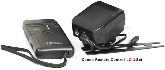
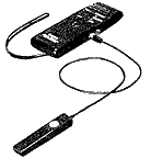
Instructions and Basic Operating
Procedure for Canon Wireless Remote Set LC-3
Wireless Remote Control Photography (mode: ![]() : Single shot,
: Single shot,
![]() continuous action sequence, or Delay mode)
continuous action sequence, or Delay mode)
1. Insert batteries. Place batteries in both transmitter and receiver.
2. Turn main switches ON. Slide the main switches of both the transmitter and receiver
away from the OFF position (-> continue with channel setting operation).
3. Check batteries. a) Receiver move main switch from OFF position to 1SR or ON. Battery OK :Indicator lamp lights for approx. 1 second. Battery power Low- Indicator lamp lights for approx. I second, then blinks or does not light at all. Transmitter Move main switch from OFF (0) position to ON; Battery OK :Ready lamp lights within 1 or 2 seconds. Battery power Low :Ready lamp lights irregularly, blinks or does not light at all.
 |
4. Set channels Set both the transmitter and receiver to the same channel (A, B, or C). Note i) When using one transmitter to operate two or three cameras in sequence, set the first camera to channel A, the second to channel B, and the third to channel C. Then change the transmitter channel switch to operate the desired cameras. ii) When operating multiple cameras at the same time, set the transmitter channel switch to ALL, and shoot (the receivers will operate on any channel setting). iii) when using two or more wireless controller sets at the same location, be sure that each set is operating on a different channel. |
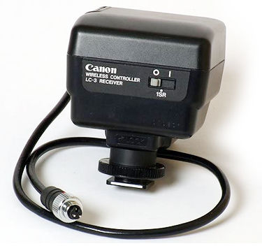
5. Mount-the receiver (a) Attach
the receiver mount to the camera accessory shoe so that the white surface on the
receiver is
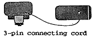
toward the back of the camera, then tighten the mounting screw. (b) Align the red
indicator mark on the three-pin connecting cord plug with the indicator on the camera
remote control socket, and connect. (c) Set direction: Rotate the receiver (range
360*) so that the receiving window is pointed towards the transmitter. Note: -When
the camera accessory shoe is taken up by a strobe flash unit, use the LC-2 bracket
to mount the receiver.
6. Select control mode. use the mode switch
to select the proper control mode for the type of photography desired.
Shoot. Press the transmitter button on the transmitter to shoot.: (a) :Single
shot (b) :Continuous action shot (c) Delay mode: Single shot after approx. 3-5 sec.
For Wireless Remote Control Photography (Test Mode)
a. Select control mode.: Use the transmitter control mode switch to select
test mode. b. Verify operation. i. OK :Half-press or full-press the
button. -> Receiver lamp lights for approx. one second.
ii. Not operating :Half-press or full-press the button. -> Receiver lamp does
not light at all. When low battery power is the cause: Receiver: Indicator lamp lights
for approx. 1 second, then blinks. Transmitter: Ready light blinks.
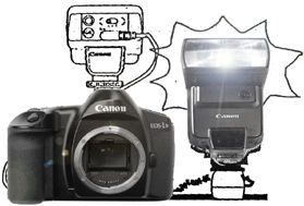
Strobe Flash Photography
1. Setup. Attach the strobe unit to the camera accessory shoe, and attach the receiver
using the accessory bracket. Then connect the receiver to the camera using the 3-pin
connecting cord. 2. Shoot. Make the desired settings, then press the transmitter
button on the transmitter to shoot.
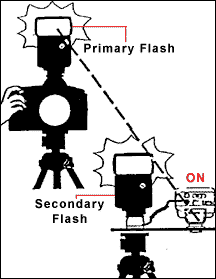
Wireless Strobe Operation for Supplementary Lighting (Using the Receiver as
a Slave Unit)
1. With Primary Light Attached to Camera (Transmitter
Not Required - see Illustration below at bottom
right.
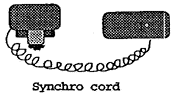
Attach the master strobe unit to the camera hot shoe. connect the receiver and the
supplementary strobe unit using a commercially available synchro cord, and turn the
receiver main switch to ON (1). When using a strobe unit without a PC terminal, use
an off-camera shoe with a commercially available PC terminal.
(a) To shoot: Press the camera shutter button directly. * Use any channel setting.
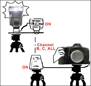
(b). Without mounting a Strobe Unit on the Camera (c Connect the camera and the transmitter
using a commercially available synchro cord.* when using a camera without a PC terminal,
use a hot shoe with a commercially available PC terminal. Connect the receiver to
the strobe using a commercially available synchro cord. When using a strobe unit
without a PC terminal, use an off-camera shoe with a commercially available PC terminal.
(d) Turn the transmitter and receiver main switches to ON (e) Set the channel switches
to B, C, or ALL.(f) To shoot: Press the camera shutter button directly.
 |
 |
Caution: -When using a wireless supplementary flash, you cannot activate the shutter by pressing the transmitter button. -> Press the camera shutter button directly. When using a wireless supplementary flash, TTL (through the lens) light adjustment is not possible -> Use the strobe in M (manual) mode. |
Verifying Shutter Release
1. By Camera Shutter Sound At relatively close range, camera release can be verified by the sound of the Shutter.
 |
2. By Strobe Flash (a) Attach the receiver to the camera accessory shoe, and connect the 3-pin connecting cord., mount the strobe unit on the accessory bracket. * When using a strobe unit without a PC terminal, use an off-camera shoe with a commercially available PC terminal. *When the strobe is attached directly to the camera, select the shutter speed carefully. The shutter speed will be affected by the synchronization of the strobe with the camera. |
 |
 |
Using Remote Control Switch 60T3 Attaching the Remote Switch 6OT3 is via plugging the connector of the 60T3 to the side of the transmitter. 1. Setup. (a) connect the remote control switch 60T3 to the transmitter remote control socket.; (b) mount the transmitter on a tripod. 2. Shoot. Press the switch on the 60T3., You can use the transmitter button with the 60T3 attached. To control from even greater distances from the transmitter, use an extension cord 100OT3 (cord length 10m). |
Signal Relay:
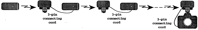
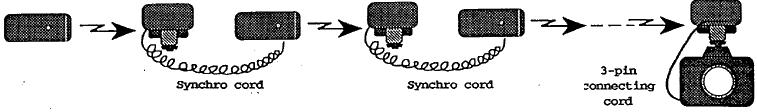
1. Receiver using 3-pin connecting cord: a- Setup i) After attaching transmitters and receivers to tripods or other fixtures using accessory brackets, attach the 3-pin connecting cord
 |
on each receiver to the next transmitter unit. ii) Attach the last receiver to the camera using the 3-pin connecting cord. |
 |
4. Power switch setting a) Normal photography Set all transmitters and receivers to ON; TO use 1SR (SW-2 signal only) Set all transmitters to ON (1), and all receivers to 1SR; Transmission Time Lag; The time lag for each transmission (transmitter -receiver pair) is approximately 0.13 seconds. Condition :Press first transmitter SW-1 and SW-2 together rapidly, with relay receivers set to SW-1 output OFF. |
Signal Relay:
2. Using commercially available synchro cord:
a. Setup. (i) After attaching transmitters and receivers to tripods or other
fixtures using accessory brackets, attach each relay receiver to the next transmitter
unit using a synchro cord. Attach the last receiver to the camera using a synchro
cord. b. Channel selection The first transmitter and the last receiver must
be set to the same channel. All relay transmitters: set to channel
A. Relay receivers: set to any channel. c. Mode selection i. Set the first
transmitter to the desired mode. ii. set the relay transmitters to any mode. d. Power
switch setting i. Set the first transmitter to ON, and the last receiver to either
ON or 1SR (SW-2 signal only) as desired. ii. Set relay transmitters to ON. iii. Switch
relay receivers from OFF to either ON or 1SR.
 |
Transmission Time Lag The time lag for each transmission (transmitter-receiver pair) is approximately 0.13 seconds. Condition :Press first transmitter SW-1 and SW-2 together rapidly, with relay receivers set to Sw-1 output OFF. |
suggestion:- Some of the good web resources (External Links) on Canon Remote
Control Accessories: -RS-60E3 Remote
Switch, TC-80N3 Remote Timer
Controller; RC-1 Infrared Wireless
Remote Control by Julian Loke
| Number | Description | Remarks | |
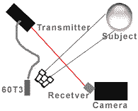
| 1. | Transmitter and receiver must be directly aligned with each other. Especially over long distances, the receiving window of the receiver must directly face transmitter. | The effective transmission distance is reduced in direct proportion to the angle between the transmitter and receiver. | |
| 2. | Place the receiver so that sunlight cannot enter the receiving window directly. | Direct sunlight can cause abnormal operation. | |
| 3. | Avoid use in areas where people, cars,etc. can pass through the transmission path. | Obstacles can hinder signal transmission. | |
| 4. | When using the LC-3 indoors, avoid using remote controls of other electronic equipment. | Remote control systems can interfere with each other. | |
| 5. | Set camera film advance to continuous feed (Examples: C, CL, CH) . | If the camera is set to single-shot mode, it will not take continuous shots even when the first transmitter is set to continuous-action .mode. | |
| 7. | Set camera focus mode to M (manual) or Al servo AF (or AF). | in single-shot AF mode, a full press of the transmitter button can fail to focus the camera, so the shutter will not release. | |
| 8. | Do not use FR6 (lithium) batteries. | Lithium batteries can damage electrical circuits and may release heat. | |
| 9. | For remote-control photography with AE, cover the viewfinder eyepiece with an eyepiece shutter or eyepiece cap. | Light entering through the viewfinder can cause incorrect exposure. | |
| 10. | When using 1SR mode with an AF camera, set the camera focus mode-to M (manual). | This is because only the SW-2 signal is transmitted. | |
| 11 | When talking only single shots, always set the transmitter to single-shot mode | In continuous -action mode; the camera my shoot several frames even from a quick press. |
Previous
Index Page of LC-3
Wireless Remote Control Set
Main Index
Page
for Canon Remote
Control
|
Questions, Issues
& Answers
| Canon
EOS-1 Series Message
Board
|
Canon EF lens Board | in a shared environment
|
Free Trade Zone | shared environment
Selective
Canon TTL Flash Models:-
160E | 200E | 300EZ | 300TL | 420EZ | 430
EZ
| 480EG | 540EZ | Macrolites | Other non-TTL Canon flash models
Useful
Resources at Julian Loke site: - Instruction Manual(s (PDF) for Canon
420EX
| 580EX AF-TTL Speedlites
|
Back | Index Page The Canon EOS-1N
Series Professional SLR camera
|
Back | Main Index Page The Canon EOS-1
Series Professional SLR camera
Background and Various
Issues
| The Basic
Features
& various Setup | Manual & Auto Focusing | Metering
Systems
| Exposure
Control
| Viewfinder
optical System
| Flash
Photography
(with Speedlite 540EZ extension) Reliability Issues:- Body
Chassis
| Shutter
Unit
| Electronic
Circuitry
| Film
Transport
& film handling Secondary Functions:-
Custom
Function
System Accessories:- Film Back Options | Macro/Close
Up| Power Sources - BP-E1 | PDB-E1 | Focusing Screens| Remote Control|
System
compatibility
Canon EOS-1N - Variants Canon EOS-1N RS | Canon/Kodak Digital
DCS-1, 3 -5 & 520/560 Series
(includes Canon D2000 - Instruction Manual links provided) Full Technical
Specification
| Main
Reference Map
/ Nomenclature
Resource Centre:-
Comparative Charts between EOS-1 & EOS-1N / or with its
active Competition(s) (Nikon); Quick
Operational Reference
Card (278k Gif File); Listings
of 7-segment
digital numbers/letters
appeared on LCD display panel/viewfinders (HTML page); External Link:-Instruction Manual (3.3MB PDF file applicable
for both Canon EOS-1N (RS)
The Eyes of EOS - EF Lenses
![]()
HOME - Photography in Malaysia
Copyright © 1998-2006. leofoo ®. MIR Web Development Team.
Volunteered Maintainer(s) for the Canon EOS-1N Series Message Board: Philip Chong, Editor, Advance Images Magazine; Vincent Thian, AP, XXXX Dummy
Special Credit:- :Mr. Richard Yeow & Mr. Simon Wong from camera division
of ![]() Marketing
Malaysia, for their continual effort in supporting development of this EOS/EF website.
Others: Dummy
Mr. Chuck Hester, US for his text re-editing skill for this site; Our staff, HowKiat® who created the 3D-Nikon F5 logo. Mr. Lew Chee Wai of YL camera for lending his F5 for me to take some shots appeared in this site.
All those nice folks who have contributed their images, in particular Mr. Mike Long, Edwin leong, Palmi
Einarsson, Sergio Pessolano, Fred Kamphues, Harry Eggens,
Curtis Forrester, Nick (Natures
Moments), Sandra Bartocha; fellow countrymen, Vincent Thian, Koh Kho King, Philip
Chong, CY Leow etc.
and contributions from a few nice folks from Photo Malaysia Forum. Disclaimers
& acknowledgments:
Certain content and images appeared in this site were either scanned from official
marketing leaflets, brochures published by Nikon and/or contribution from surfers
who claimed originality of their own work for public publishing in this website,
where majority of the extracted information are used basing on educational merits.
The creator of this site will not be responsible for any discrepancies that may arise
from any possible dispute except rectifying them after verification from respective
source. Neither Nikon or its associates has granted any permission(s) in using their
public information nor has any interest in the creation of this site. "Canon", "EOS",
"EF" "RT", "EOS-1n RS", "Booster
Drive E1" & other
applicable technical/business terms are registered trade name(s) of Canon Inc., Japan.
Site made with an Apple G5 IMac.
Marketing
Malaysia, for their continual effort in supporting development of this EOS/EF website.
Others: Dummy
Mr. Chuck Hester, US for his text re-editing skill for this site; Our staff, HowKiat® who created the 3D-Nikon F5 logo. Mr. Lew Chee Wai of YL camera for lending his F5 for me to take some shots appeared in this site.
All those nice folks who have contributed their images, in particular Mr. Mike Long, Edwin leong, Palmi
Einarsson, Sergio Pessolano, Fred Kamphues, Harry Eggens,
Curtis Forrester, Nick (Natures
Moments), Sandra Bartocha; fellow countrymen, Vincent Thian, Koh Kho King, Philip
Chong, CY Leow etc.
and contributions from a few nice folks from Photo Malaysia Forum. Disclaimers
& acknowledgments:
Certain content and images appeared in this site were either scanned from official
marketing leaflets, brochures published by Nikon and/or contribution from surfers
who claimed originality of their own work for public publishing in this website,
where majority of the extracted information are used basing on educational merits.
The creator of this site will not be responsible for any discrepancies that may arise
from any possible dispute except rectifying them after verification from respective
source. Neither Nikon or its associates has granted any permission(s) in using their
public information nor has any interest in the creation of this site. "Canon", "EOS",
"EF" "RT", "EOS-1n RS", "Booster
Drive E1" & other
applicable technical/business terms are registered trade name(s) of Canon Inc., Japan.
Site made with an Apple G5 IMac.
Additional
information on other EOS AF-SLR Models:
EOS-650 (1987.2) | EOS-620 (1987.5) | EOS-750QD (1988.10) | EOS-850QD (1988.10) | EOS-630QD (1989.4) | EOS-1 (1989.9) | EOS-RT (1989.10) | EOS-700QD (1990.3) | EOS-10S QD (1990.3) | Canon T-60 | EOS-1000F /Rebel S QD (1990.9) | EOS-100 / Elan QD (1991.9) | Canon EF-M (1991.9) | EOS-5/A2E QD (1992.10) | EOS-1000FN /Rebel S II QD (1992.4) | EOS-500 / Rebel XS / KISS (1993.10) | CANON EOS-1n (1994.9) | EOS-888/5000QD (1995.1) | EOS-1n RS (1995.3) | EOS-50/50E / Elan II(E) /EOS 55 (1995.9) | EOS -500N / Rebel G / KISS II (1996.9) | EOS-IX (1996.10)
/ EOS-IX Lite /IX-7 (1996.3) | EOS-3 (1998.11) | EOS-88/3000
(1999.3) | EOS-300 / Rebel 2000 QD / KISS III (1999.4)
| EOS-1v (2000.3) | EOS-30 / EOS-7 / EOS Elan 7E (2000.10)
| EOS-3000N /EOS-66 / Rebel XS-N (2002.2) | EOS-300V / Rebel
Ti / KISS V (2002.9) | EOS 3000V / Rebel K2 / KISS Lite
(2003.9)
Main Index page
- Canon EOS-1N AF 35mm SLR camera